

")

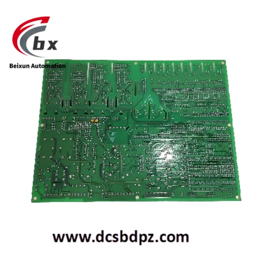
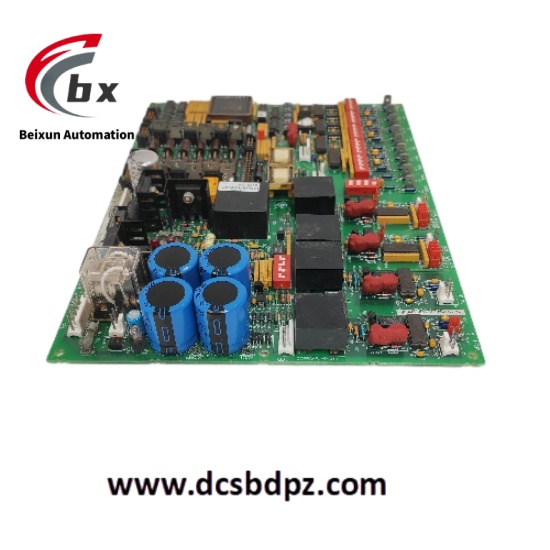
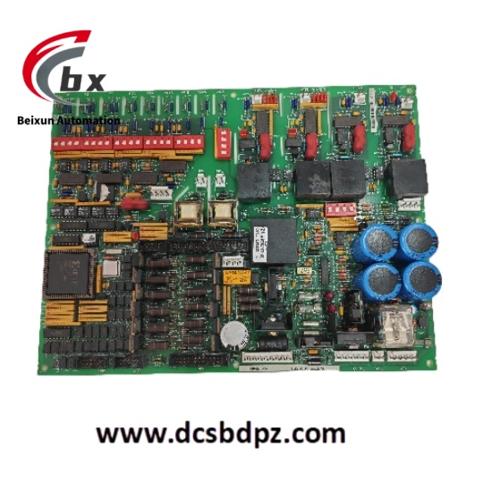
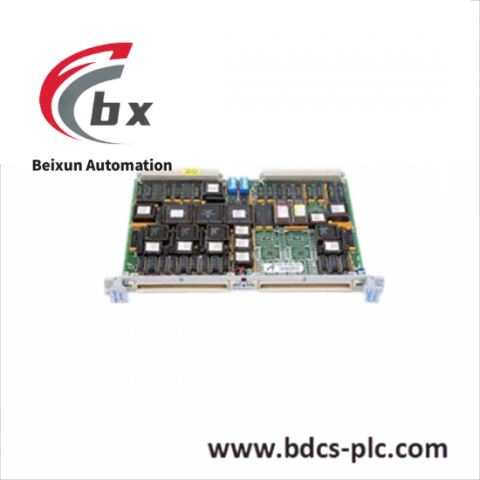
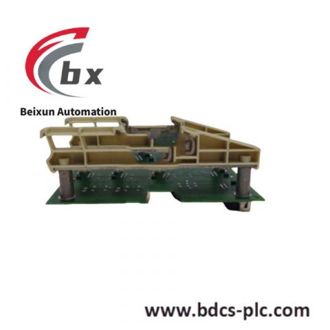
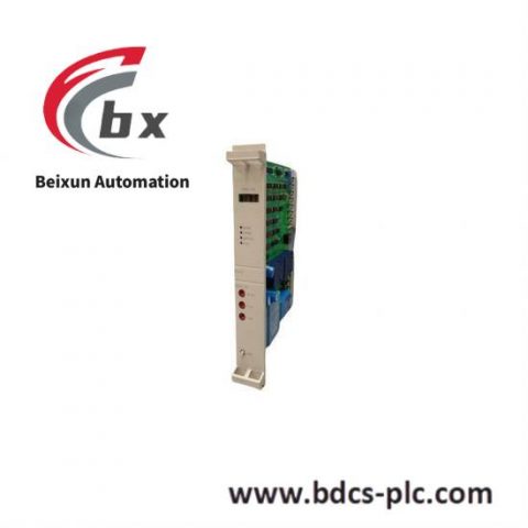
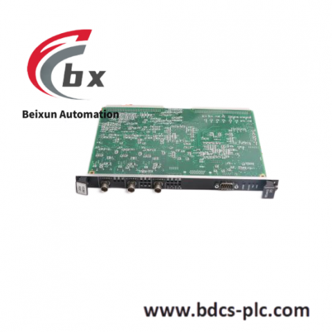
GE DS200DCFBG2BNC MRP420024 Power supply and feedback control board
Specific Parameters
- Input Power: 38V AC and 115V AC (24V DC in EX2000 applications)
- Output Power: Supplies control – level power to the drive and outputs 115V AC power to the enclosure fans (not applicable in EX2000 applications)
- Voltage – Current Feedback VCO Circuit: The voltage – controlled oscillator (VCO) circuit on the board converts the input voltage into a frequency signal. The nominal output frequency of each VCO is 250kHz. Depending on the input voltage, the output frequency ranges from 0 to 500kHz. Through the 1PL connection, the VCO output is transmitted to the SDCC / LDCC board to provide feedback
- Power Supply: Equipped with circuits for powering the drive and related equipment
- Signal Connection: Features 18 pin connectors and 9 tab connectors for handling various signals
- Diagnosis and Protection: Built – in diagnostic functions and fuses to ensure system safety; equipped with DIP switches for precise adjustment of voltage settings
Product Performance
- Stable Power Supply Capacity: It can stably obtain external input power and provide reliable control – level power for the drive, meeting the power requirements for the stable operation of equipment. It can ensure the continuity and stability of power supply in different application scenarios.
- Precise Feedback Regulation: With the help of the VCO circuit, it converts the input voltage into a frequency signal and transmits feedback signals to the SDCC / LDCC board for DC motor and voltage control, realizing precise monitoring and regulation of the system operation status and ensuring that the equipment operates in the best state.
- Flexible Signal Processing: The 18 pin connectors and 9 tab connectors enable diverse signal processing, can flexibly connect different devices and lines, and adapt to complex system architectures and diverse signal transmission requirements.
- Reliable Diagnosis and Protection: The built – in diagnostic functions and fuses can monitor the system operation status in real – time. When an abnormality occurs, the protection mechanism can be quickly activated to prevent the expansion of faults and ensure system safety. The setting function of the DIP switch provides users with a way to accurately adjust the voltage according to actual needs, improving the adaptability and stability of the system.


There are no reviews yet.